What Are Load Banks?
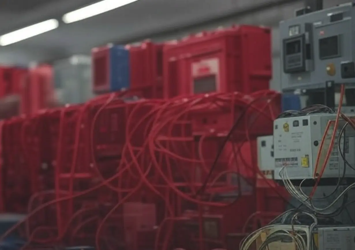
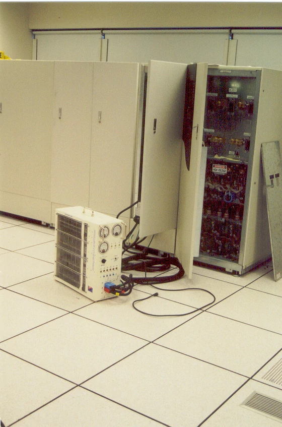
A load bank is a specialized device that simulates an electrical load by converting electrical energy into a controlled load through resistance, inductance, or capacitance. It applies this load to a power source, transforming the energy into an electric or magnetic field and dissipating the resulting power output as heat.
Load banks are constructed with load elements, protective features, incremental controls, metering, and accessories necessary for operation. They are primarily used to test power sources, such as standby generators and batteries, ensuring reliability under various conditions. Typically cooled by an electric motor and fan delivering the required cubic feet per minute (CFM) of airflow, load banks evaluate how critical systems respond to load changes.
Unlike real-world loads, which are often dispersed, unpredictable, and variable, a load bank provides a precise, organized, and fully controllable load. This allows it to accurately replicate the operational demands a power source will encounter in actual applications.
Why Conduct Load Bank Tests?
Load bank testing ensures backup power reliability, ensuring backup power systems, such as generators and UPS units, perform reliably during outages. Conducting tests in a controlled environment uncovers issues before they cause failures. Testing is essential during system commissioning and as part of ongoing maintenance.
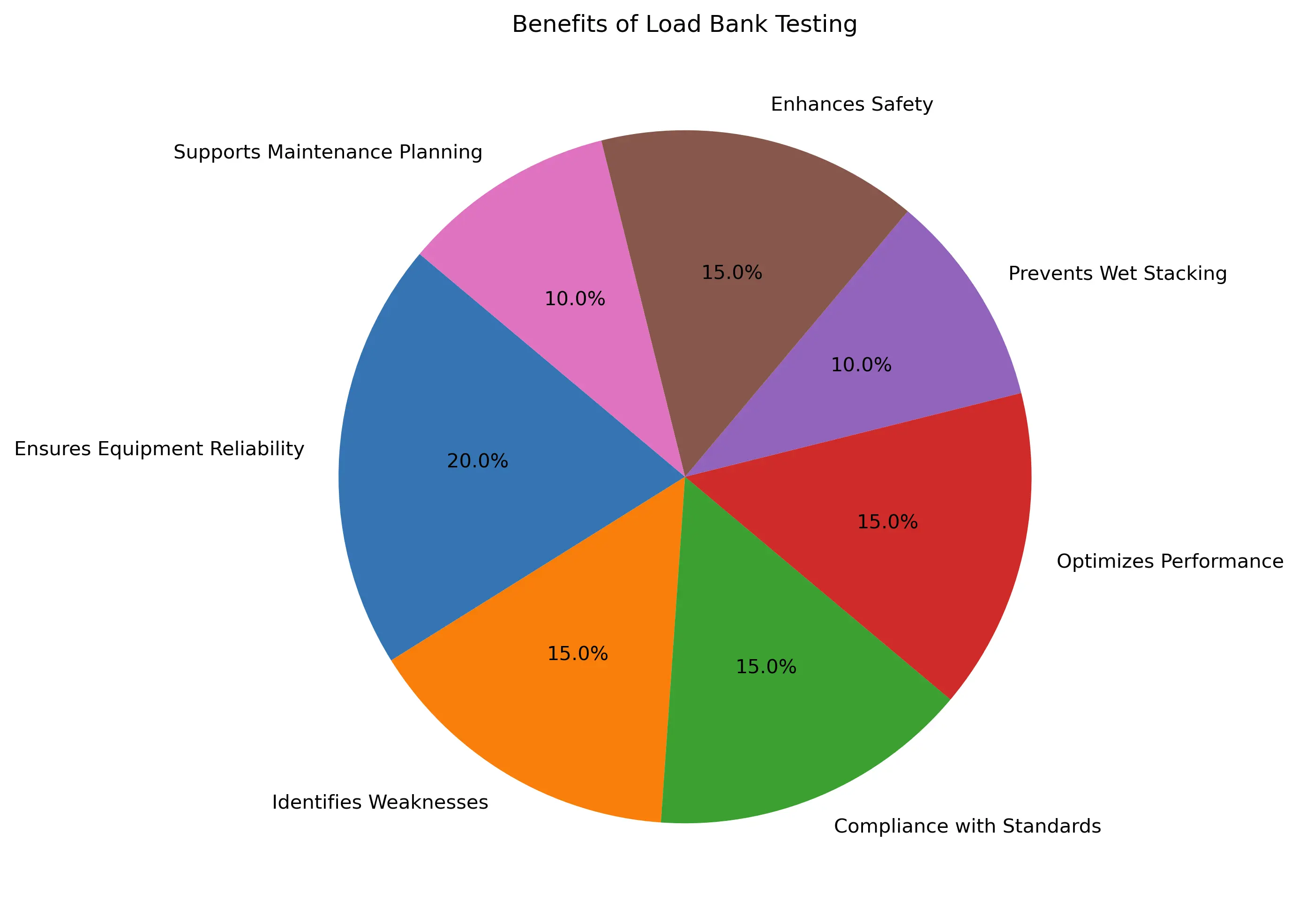
Key Benefits of Load Bank Testing:
1. Verifies System Reliability: Load bank testing is the only way to confirm a backup power system can handle full-power loads. Systems may function under light loads but fail under stress without regular testing.
2. Prevents Wet Stacking in Generators: Prolonged operation under light loads can cause diesel generators to develop “wet stacking,” where unburned fuel or carbon builds up in the exhaust system. This reduces efficiency and risks permanent damage. Running the generator at sufficient load for a few hours corrects this issue.
3. Ensures Standards Compliance: Standards like the National Fire Protection Association (NFPA) Standard for Emergency and Standby Power Systems, ANSI/NETA Standard for Maintenance Testing Specifications, and Joint Commission requirements mandate load testing for commissioning and maintenance.
4. Tests Integrated Systems: During data center commissioning, load banks simulate the heat load of critical electrical systems to test mechanical cooling systems. Water-cooled load banks verify chiller plants meet design specifications. Integrated system testing reveals issues that component-level or factory testing may miss.
Why It Matters: Regular load bank testing ensures backup power systems are ready for emergencies, minimizes downtime, and protects critical operations. It helps maintain compliance, optimize performance, and avoid costly failures.
What Happens During a Load Bank Test?
Load bank testing validates the performance and battery autonomy of Uninterruptible Power Supply (UPS) systems and generators under load conditions. Conducted during preventative maintenance, it ensures reliable operation. For UPS systems, it also identifies weak battery cells in battery strings, enabling proactive replacement of cells nearing the end of their lifespan or failing to hold a charge.
Suppliers of power protection equipment often provide load bank testing, sometimes during UPS commissioning. However, testing should occur at least one week after commissioning to allow battery voltages to stabilize and ensure full charging. Early testing may yield inaccurate results, wasting time and resources.
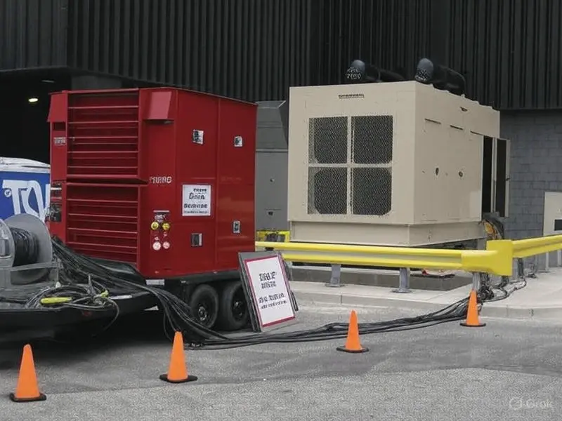
A generator load bank test assesses and verifies that all primary components—engine, alternator, and controls—are functioning correctly. Specialized equipment applies artificial loads, bringing the generator to optimal operating temperature and pressure. This is critical for standby or emergency generators that rarely run or operate below 30% of their rated kilowatt (kW) capacity.
A proper load bank test confirms that a generator can deliver its maximum rated power while maintaining stable temperature and pressure levels for extended periods. This ensures reliability during emergencies, especially for generators not regularly operating at full kW capacity, by simulating real-world demands.
Benefits of Load Bank Testing
Annual load bank testing is essential to ensure the backup power reliability and performance of UPS systems and generators. Regular testing helps identify issues early and maintains optimal operation. Key benefits include:
1. Verifies System Performance: Confirms that the UPS or generator can handle its full rated load, ensuring dependable operation during critical situations.
2. Wet Stacking Prevention in Generators: Prolonged operation under light loads can cause diesel generators to develop "wet stacking," where unburned fuel or carbon builds up in the exhaust system. This reduces efficiency and risks permanent damage. Running the generator at sufficient load for a few hours corrects this issue.
3. Early Problem Detection: Identifies potential issues before they escalate, reducing repair costs and preventing major system failures.
4. Ensures Cooling System Efficiency: Validates that cooling systems perform effectively under load, preventing overheating during extended operation.
5. Supports Commissioning: Facilitates the commissioning of turbines and diesel generators, ensuring they meet operational standards before deployment.
6. Reduces Wet Stacking: Mitigates wet stacking in diesel generators by allowing engines to reach optimal operating temperatures, improving efficiency and longevity.
7. Optimizes Load Management: Enhances load distribution in prime power applications, ensuring balanced and efficient power delivery.
Industries Served By Load Banks
Applications in Alternative Energy and Power Systems
| Alternative |
Battery Systems |
Fuel Cells |
Diesel Generators |
UPS's |
Healthcare |
Maritime |
Power Electronics |
DOD |
| Wind Farms |
Switchgear |
Sales / Service |
Sales / Service |
Sales / Service |
Hospitals |
Shipyards |
Testing Labs |
Submarines |
| Solar |
Valve Regulated |
Manufacturing |
Manufacturing |
Manufacturing |
Pharmaceuticals |
Drydock |
Universities |
Port Power |
| Geothermal |
Gel |
Controls |
Controls |
Controls |
Surgery Centers |
Cruise Ships |
Automation |
Base Ports |
| Hydro |
Chargers |
Solid Oxide |
Hydroelectric |
IST |
Treatment Facilities |
Power Barge |
Automobile |
DOE |
| Tidal |
Flooded |
Proton Exchange |
Blackstart |
Batteries |
Nursing Homes |
Workboats |
Rail and Transit |
R&D |
| Wave |
Sales / Service |
Alkaline Fuel Cell |
Supermarkets |
N/A |
Urgent Care |
Cold Ironing |
Power Supplies |
GSA |
| Biomass |
Manufacturing |
Direct Methanol |
Water Treatment |
N/A |
Blood Banks |
Shorepower |
N/A |
N/A |
Applications in Industrial and Infrastructure Sectors
| Aerospace |
Oil & Gas |
Utilities |
Mining |
Telecom |
Commercial |
Turbines |
Data Centers |
Nuclear |
| NASA |
FPSO |
CHP |
Generators |
Cell Towers |
Electrical Contractor |
Sales / Service |
Building Owner |
UPS |
| Aircraft |
Rigs |
Island Grid |
Blackstart |
Standby Power |
General Contractor |
Manufacturing |
Container |
Batteries |
| Military |
Refineries |
Switchgear |
UPS |
Switchgear |
Commissioning Firms |
Controls |
Colocation |
Generators |
| Airport |
LNG Plant |
Blackstart |
Switchgear |
Batteries |
Engineering Firms |
Blackstart |
Blackstart |
Controls |
| N/A |
N/A |
Substation |
N/A |
N/A |
Defense Contractors |
Hydroelectric |
Facilities |
Blackstart |
| N/A |
N/A |
Excitation |
N/A |
N/A |
N/A |
N/A |
IST |
IST |
Frequently Asked Questions
1. What is a load bank?
A load bank is a device that simulates an electrical load to test power sources like generators and UPS systems, ensuring reliability under various conditions.
2. Why is load bank testing important?
Load bank testing verifies system performance, ensures backup power reliability, prevents wet stacking in generators, ensures compliance with standards, and identifies issues before failures occur.
3. What types of load banks are best for generators?
Resistive load banks are ideal for testing generator capacity and prime mover performance at unity power factor. For realistic load conditions, resistive/reactive load banks simulate mixed loads, while inductive load banks are suitable for testing motor-driven systems.
4. How often should load bank testing be performed?
Load bank testing should be conducted during system commissioning and at least annually as part of preventive maintenance to ensure ongoing reliability and compliance with standards like NFPA 110.
5. Can load banks test UPS systems?
Yes, load banks, particularly resistive and electronic load banks, are used to test UPS systems, verifying their ability to handle full loads and identifying weak battery cells for proactive maintenance.
Load Bank Types
Load banks are critical tools for testing power systems, simulating various electrical load conditions to evaluate the performance of generators, UPS systems, and other power equipment. The primary types include resistive, inductive, and capacitive load banks, each designed to replicate specific load characteristics. Inductive and capacitive load banks introduce reactance, which opposes alternating current (AC) due to the buildup of electric or magnetic fields in circuit elements like inductors or capacitors. Reactance, the imaginary component of impedance, measures a circuit element’s resistance to AC signals at a given frequency, enabling testing of complex power system behaviors under diverse conditions.
Key Features:
- Diverse Load Simulation: Different load bank types allow testing under resistive (in-phase), inductive (lagging), or capacitive (leading) conditions, covering a wide range of real-world scenarios.
- Reactance in AC Circuits: Inductive and capacitive load banks create phase shifts between voltage and current, essential for evaluating system response to reactive loads.
- Comprehensive Testing: Supports assessment of power system stability, efficiency, and compliance across various applications, from industrial to high-tech environments.
Applications:
- Power System Validation: Tests generators, UPS systems, and distribution networks to ensure reliable operation under simulated load conditions.
- Commissioning and Maintenance: Verifies new installations and supports routine maintenance to prevent failures in critical power systems.
- Power Quality Analysis: Evaluates the impact of reactive loads and harmonics, supporting compliance with standards like IEEE 519 and NFPA 110.
Considerations:
- Load Type Selection: Choose the appropriate load bank type based on the system and load conditions being tested to ensure accurate simulation.
- System Compatibility: Verify that the load bank’s voltage, power, and frequency ratings match the system under test to avoid damage or inaccurate results.
- Power Factor Configuration: When testing reactive loads, adjust settings to achieve the desired power factor, ensuring realistic simulation of operational conditions.
- Environmental Conditions: Account for site-specific factors, such as temperature or ventilation, that may affect load bank performance during testing.
- Technical Expertise: Requires skilled operators to configure load banks, interpret results, and ensure safety, particularly for tests involving reactive loads and phase shifts.
Load banks are indispensable for power system testing, offering tailored solutions to simulate diverse load conditions and ensure reliability, efficiency, and compliance across various applications.
Resistive Load Banks
Resistive load banks are the most common type of load bank, designed to provide equivalent loading for both generators and their prime movers. For each kilowatt (or horsepower) of load applied to the generator, an equal load is transferred to the prime mover, effectively testing the entire power generation system. By converting electrical energy into heat through high-power resistors (e.g., wire-wound resistors), these load banks remove energy from the system, impacting the generator, prime mover, fuel consumption, and associated components like cooling and exhaust systems.
Key Features:
- Equivalent System Loading: Applies balanced loads to both the generator and prime mover, ensuring comprehensive testing of the entire power generation chain.
- In-Phase Operation: Produces a voltage drop in-phase with the current, simulating pure resistive loads with a unity power factor (1.0).
- Heat Dissipation: Converts electrical energy to heat, dissipated via air (forced or convection) or water-cooling systems, requiring robust thermal management.
- High Reliability: Utilizes durable resistors, symbolized as “R” and measured in ohms (Ω), to provide consistent and repeatable load testing.
Applications:
- Generator Testing: Validates the performance and capacity of generators, ensuring they can handle rated loads for applications like data centers, hospitals, or industrial facilities.
- Prime Mover Evaluation: Tests the efficiency and reliability of engines or turbines under load, assessing fuel consumption and mechanical performance.
- Commissioning and Maintenance: Verifies new power system installations and supports routine maintenance to prevent failures in standby or primary power systems.
- UPS System Testing: Evaluates uninterruptible power supply (UPS) systems under resistive loads, ensuring reliable backup power for critical infrastructure.
- Power System Certification: Supports compliance testing to meet standards like NFPA 110 for emergency and standby power systems.
Technical Details:
- Resistance Mechanism: Resistance acts as friction against current flow, converting electrical energy into heat through high-power resistors.
- Power Factor: Operates at a unity power factor (1.0), with voltage and current in-phase, ideal for testing systems under pure resistive conditions.
- Heat Management: Requires effective cooling (air or water) to dissipate heat generated by resistors, ensuring safe and sustained operation.
Considerations:
- Cooling Requirements: Ensure adequate air or water-cooling systems to manage heat output, particularly for high-power or prolonged testing.
- System Compatibility: Verify that the load bank’s voltage, power, and frequency ratings align with the system under test to avoid damage or inaccurate results.
- Environmental Conditions: Account for site-specific factors, such as temperature, humidity, or ventilation, that may affect cooling efficiency and load bank performance.
- Technical Expertise: Requires operators with knowledge of power systems and load testing to configure tests and interpret results accurately.
- Safety Protocols: Implement proper grounding, thermal monitoring, and overcurrent protection to prevent overheating or electrical hazards during testing.
Resistive load banks are essential for comprehensive power system testing, providing reliable and repeatable load simulation to ensure the performance and durability of generators, prime movers, and associated systems in diverse applications.
Reactive Load Banks
Reactive load banks are specialized testing devices designed to simulate reactive loads, which oppose alternating current (AC) due to the buildup of electric or magnetic fields in circuit elements like inductors or capacitors. These load banks produce reactance—either inductive (positive) or capacitive (negative)—resulting in currents that are out of phase with voltage. By replicating real-world reactive load conditions, they enable comprehensive testing of power systems to ensure stability and performance in industrial and commercial environments.
Key Features:
- Reactive Load Simulation: Generates inductive (lagging) or capacitive (leading) loads to mimic the behavior of real-world circuit elements, such as motors, transformers, or capacitors.
- Flexible Power Factor Testing: Allows precise control of power factor by combining with resistive load banks, enabling testing at various phase angles (e.g., 0.8 lagging or leading).
- High Precision: Provides accurate simulation of reactance, measured as the imaginary part of electrical impedance, to evaluate system response to phase shifts and harmonic effects.
- Robust Design: Engineered to handle complex electrical interactions, ensuring reliable performance in high-power testing scenarios.
Applications:
- Industrial Power Systems: Tests systems with mixed resistive and reactive loads, such as those in manufacturing plants with motors, transformers, or variable frequency drives (VFDs).
- Power System Commissioning: Validates the performance of generators, UPS systems, and distribution networks under reactive load conditions during installation.
- Power Quality Analysis: Assesses the impact of reactive loads on system stability, supporting compliance with standards like IEEE 519 for harmonic and power factor management.
- Renewable Energy Testing: Evaluates inverters and power systems in solar or wind applications, where reactive loads are common due to power electronics.
- Motor and Capacitor Testing: Simulates the inductive or capacitive effects of motors and capacitor banks, ensuring reliable operation under real-world conditions.
Technical Details:
- Reactance Types: Inductive reactance (positive, lagging power factor) opposes current changes via magnetic fields, while capacitive reactance (negative, leading power factor) opposes voltage changes via electric fields.
- Phase Displacement: Reactive loads cause a voltage drop out of phase with the current (90° for pure reactance), with reactance (X) measured in ohms (Ω).
- Power Factor Control: Combining reactive and resistive loads allows testing at specific power factors, replicating real-world load profiles.
Considerations:
- Load Configuration: Carefully adjust inductive or capacitive elements to achieve the desired power factor and reactance profile, as improper settings may lead to inaccurate test results.
- System Compatibility: Ensure the load bank’s voltage, power, and frequency ratings align with the system under test to prevent damage or unreliable outcomes.
- Environmental Conditions: Account for site-specific factors, such as temperature or ventilation, that may affect the performance of reactive elements during testing.
- Technical Expertise: Requires skilled operators with knowledge of power systems, reactance, and impedance to design tests and interpret results effectively.
- Safety Protocols: Implement proper grounding, overcurrent protection, and monitoring to manage high-power reactive loads safely, preventing electrical hazards.
Reactive load banks are essential for testing power systems under realistic reactive conditions, ensuring reliability, efficiency, and compliance in industrial, commercial, and renewable energy applications.
Inductive Load Banks
Inductive load banks are specialized testing devices that produce lagging power factor loads, typically using iron-core or air-core wound reactive elements. When combined with resistive load banks, they create a lagging power factor load, simulating real-world mixed commercial and industrial loads. These load banks are essential for testing power systems under conditions that mimic the inductive effects of equipment like motors and transformers, ensuring system stability and performance.
Key Features:
- Lagging Power Factor Simulation: Generates inductive loads that produce a lagging power factor, replicating the electrical behavior of inductive equipment.
- Standardized Ratios: Typically rated at 75% of the resistive load (e.g., 75 kVAr inductive for 100 kW resistive) to achieve a 0.8 power factor, with customizable ratios for other power factor ratings.
- Flexible Configuration: Can be paired with resistive or capacitive load banks to create complex load profiles for comprehensive system testing.
- High Precision: Provides accurate simulation of inductive effects, enabling reliable evaluation of power system response to lagging loads.
Applications:
- Motor and Transformer Testing: Simulates the inductive loads of motors, transformers, and other equipment, ensuring power systems can handle lagging power factor conditions.
- Commercial Load Simulation: Replicates mixed commercial loads, such as those from lighting, heating, and motor-driven systems, in facilities like office buildings, factories, or retail centers.
- Generator and UPS Testing: Validates the performance of generators and uninterruptible power supplies (UPS) under inductive load conditions, ensuring stability and efficiency.
- Power System Commissioning: Tests power distribution systems during installation to confirm their ability to manage inductive loads typical of industrial or commercial environments.
- Power Quality Analysis: Assesses the impact of lagging power factor loads on system performance, supporting compliance with standards like IEEE 519.
Technical Details:
- Phase Displacement: Inductive loads cause a voltage drop that is 90° out of phase with the current, with reactance (symbolized as “X”) measured in ohms (Ω).
- Power Factor Control: Combining inductive and resistive loads allows precise control of power factor, typically set to 0.8 for standard testing, but adjustable for specific requirements.
Considerations:
- Load Ratio Configuration: Carefully set the inductive-to-resistive load ratio to achieve the desired power factor, as incorrect settings may lead to inaccurate test results.
- System Compatibility: Ensure the load bank’s voltage, power, and frequency ratings align with the system under test to prevent damage or unreliable outcomes.
- Environmental Conditions: Account for site-specific factors, such as temperature or ventilation, that may affect the performance of iron-core or air-core reactive elements.
- Technical Expertise: Requires skilled operators with knowledge of power systems and inductive load dynamics to design tests and interpret results effectively.
- Safety Protocols: Implement proper grounding and monitoring to manage high-power inductive loads safely, preventing electrical hazards during testing.
Inductive load banks are vital for testing power systems under realistic lagging power factor conditions, ensuring reliability and performance in commercial, industrial, and utility applications.
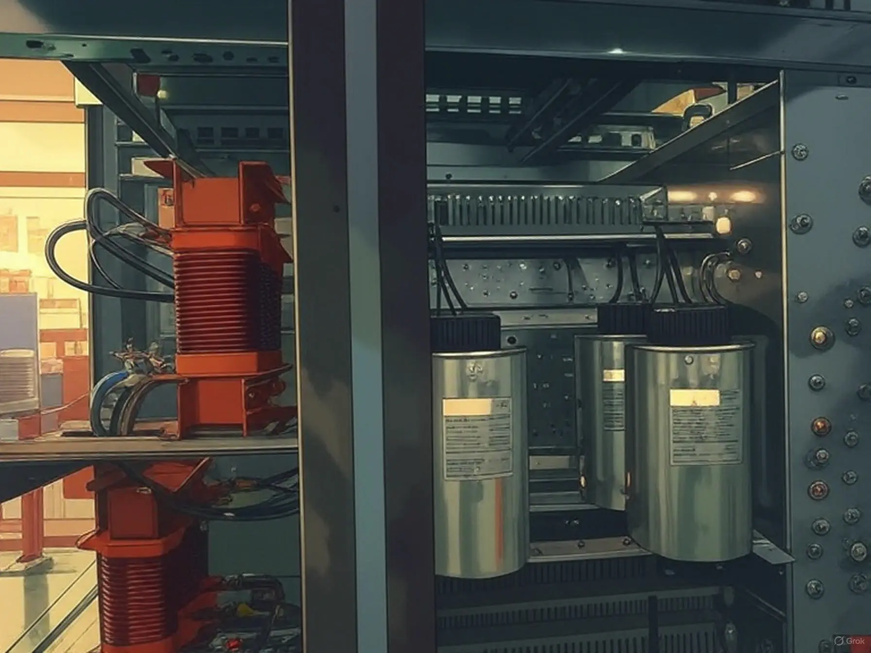
Capacitive Load Banks
Capacitive load banks are specialized testing devices that produce leading power factor loads, typically using multiple metal plates separated by a dielectric or air-core wound reactive elements. When paired with resistive load banks, they create a leading power factor load, simulating the electrical behavior of certain electronic or non-linear loads. These load banks are critical for testing power systems in environments where harmonic currents and leading power factors are prevalent, such as telecommunications and data centers.
Key Features:
- Leading Power Factor Simulation: Generates capacitive loads that produce a leading power factor, mimicking the behavior of non-linear and electronic loads.
- Harmonic Current Replication: Simulates harmonic currents generated by non-linear loads, enabling testing of power system resilience to voltage distortion.
- Flexible Configuration: Can be combined with resistive or inductive load banks to create complex load profiles for comprehensive system testing.
- High Precision: Provides accurate simulation of capacitive and harmonic effects, ensuring reliable evaluation of power system performance.
Applications:
- Telecommunications Systems: Tests power supplies and UPS systems under capacitive load conditions, ensuring reliability for telecom networks with non-linear loads like servers and routers.
- Data Centers: Evaluates the performance of power distribution systems handling electronic loads, such as computers, printers, and electronic lighting ballasts, which generate harmonic currents.
- UPS and Inverter Testing: Validates the stability of uninterruptible power supplies (UPS) and inverters under leading power factor and harmonic conditions typical of modern IT equipment.
- Power Quality Analysis: Supports compliance testing to standards like IEEE 519, assessing the impact of harmonic distortion on power systems and connected equipment.
- Variable-Speed Drive Testing: Simulates the capacitive effects of variable frequency drives (VFDs), ensuring power systems can handle associated harmonic currents.
Considerations:
- Load Profile Calibration: Configure the capacitive load bank to accurately replicate the specific power factor and harmonic profile of the target application to avoid misleading test results.
- System Compatibility: Ensure the load bank’s voltage, power, and frequency ratings align with the system under test to prevent damage or inaccurate outcomes.
- Harmonic Mitigation: Plan for harmonic filters or other mitigation strategies to protect equipment during testing, especially in sensitive environments like data centers.
- Environmental Conditions: Account for site-specific factors, such as temperature or ventilation, that may affect load bank performance during high-power testing.
- Technical Expertise: Requires skilled operators with knowledge of power quality, harmonics, and capacitive load dynamics to design tests and interpret results effectively.
Capacitive load banks are essential for testing power systems in environments with non-linear and electronic loads, ensuring reliability, power quality, and compliance in telecommunications, data centers, and other high-tech industries.
Resistive/Reactive Load Banks
Resistive/reactive load banks combine resistive and inductive (or sometimes capacitive) elements within a single chassis, enabling comprehensive testing of power systems. By supplying impedance that creates currents out of phase with voltage, these load banks simulate real-world load conditions, allowing for thorough performance evaluation of critical components like generators, voltage regulators, and switchgear. They are essential for testing systems under diverse electrical scenarios, including those requiring phase displacement and harmonic analysis.
Key Features:
- Combined Load Elements: Integrates resistive and reactive (inductive or capacitive) components to replicate complex load profiles, including out-of-phase currents.
- Versatile Testing: Enables full power system testing, evaluating performance under resistive, inductive, or combined load conditions.
- High Precision: Provides accurate load simulation for detailed analysis of system stability, efficiency, and response to dynamic loads.
- Robust Design: Built to handle high-power and complex electrical interactions, ensuring reliability in industrial and utility applications.
Applications:
- Motor Load Simulation: Replicates the electrical characteristics of motor-driven loads, testing system performance under inductive conditions.
- Q-Factor Resonance Testing: Evaluates resonant circuits and quality factor (Q) for applications requiring precise harmonic and reactive power analysis.
- RLC Network Simulation: Simulates resistive-inductive-capacitive (RLC) networks to assess power system behavior in complex electrical environments.
- Anti-Islanding Commissioning: Supports UL1741 and IEEE 1547 compliance testing for distributed generation systems, verifying anti-islanding capabilities of inverters in solar or wind applications.
- Power System Validation: Tests generators, voltage regulators, load tap changers, conductors, and switchgear to ensure reliable operation under varying load conditions.
Considerations:
- Load Configuration: Carefully adjust resistive and reactive elements to match the specific load profile required for accurate testing, as improper settings may skew results.
- System Compatibility: Ensure the load bank’s voltage, power, and frequency ratings align with the system under test to prevent damage or inaccurate outcomes.
- Environmental Conditions: Account for site-specific factors, such as temperature or ventilation, that may affect load bank performance during high-power testing.
- Technical Expertise: Requires skilled operators with knowledge of power systems and reactive load dynamics to design tests and interpret results effectively.
- Safety Protocols: Implement proper grounding, overcurrent protection, and monitoring to manage high-power and reactive loads safely, preventing electrical hazards.
Resistive/reactive load banks are critical for comprehensive power system testing, enabling precise evaluation of performance and compliance in diverse applications, from industrial facilities to renewable energy systems.
Electronic Load Banks
Electronic load banks are advanced, programmable testing devices designed to simulate solid-state loads with precise control over power and current. Available in air-cooled or water-cooled configurations, they offer dynamic load profiles to test a wide range of electrical components and systems under real-world conditions. Unlike traditional resistive load banks, electronic load banks can replicate complex load behaviors, such as high peak currents and low power factor loads, to fully stress-test equipment.
Key Features:
- Programmable Operation: Supports multiple modes—constant current, constant voltage, constant power, constant resistance, and pulse frequency/short circuit—for versatile testing scenarios.
- Dynamic Load Simulation: Mimics real-world conditions, including switching DC/AC converters, to evaluate equipment performance under worst-case operating conditions.
- High Precision: Provides accurate and repeatable load application, ensuring reliable test results for sensitive power systems and components.
- AC and DC Compatibility: Available in both AC and DC models to suit diverse testing needs, from power supplies to battery systems.
Applications:
- Power Supply Testing: Validates the performance of AC and DC power supplies, ensuring stability under varying load conditions, including low power factor scenarios.
- Battery and Fuel Cell Testing: Assesses the capacity, efficiency, and discharge characteristics of batteries and fuel cells for applications like telecommunications, electric vehicles, and renewable energy.
- Component Testing: Tests active and passive current-carrying devices, such as switches, circuit breakers, fuses, connectors, and power semiconductors, under dynamic load conditions.
- UPS System Evaluation: Simulates real-world loads to verify the reliability of uninterruptible power supplies (UPS) in data centers, hospitals, or industrial facilities.
- R&D and Certification: Supports the development and certification of power electronics by replicating complex load profiles during product design and compliance testing.
Modes of Operation:
- Constant Current: Maintains a steady current load to test system response to fixed current draw.
- Constant Voltage: Applies a consistent voltage load to evaluate performance under stable voltage conditions.
- Constant Power: Simulates a fixed power draw, critical for testing power supply efficiency.
- Constant Resistance: Mimics a resistive load with fixed resistance, suitable for basic load testing.
- Pulse Frequency/Short Circuit: Generates pulsed or short-circuit loads to stress-test equipment under transient or fault conditions.
Considerations:
- Load Profile Configuration: Carefully program the load bank to match the specific load characteristics of the equipment under test, ensuring accurate simulation of real-world conditions.
- System Compatibility: Verify that the load bank’s voltage, current, and power ratings align with the device or system being tested to avoid damage or inaccurate results.
- Cooling Requirements: Ensure adequate air or water cooling to manage heat generated during high-power testing, particularly for prolonged tests.
- Technical Expertise: Requires skilled operators with knowledge of power electronics and load dynamics to design tests and interpret results effectively.
- Safety Protocols: Implement proper grounding, overcurrent protection, and monitoring to prevent electrical hazards during dynamic or short-circuit testing.
Electronic load banks are essential for precision testing of modern power systems and components, offering unparalleled flexibility to simulate complex, real-world conditions and ensure reliability and performance.
Direct Current Load Banks
Direct current (DC) load banks are specialized testing devices designed to evaluate the performance and capacity of DC power systems, such as uninterruptible power supply (UPS) battery strings and telecommunications power supplies. By simulating real-world DC loads, these load banks perform acceptance and capacity tests to verify whether a battery can deliver the manufacturer’s rated discharge current for a specified duration under defined conditions.
Key Features:
- Constant Current/Power Discharge: Discharges batteries at a consistent current or power level to a predefined end-of-discharge voltage, enabling accurate capacity measurement.
- High Precision Testing: Measures actual discharge time against manufacturer ratings to determine battery capacity and performance reliability.
- Compact and Portable: Designed for easy deployment in various settings, including data centers, telecom facilities, and field operations.
- Safety Mechanisms: Equipped with features like overvoltage protection and thermal monitoring to ensure safe operation during testing.
Applications:
- UPS Battery Testing: Verifies the capacity and reliability of battery strings in UPS systems, ensuring uninterrupted power for critical infrastructure like data centers and hospitals.
- Telecom Power Systems: Tests DC power supplies in telecommunications networks, confirming their ability to support continuous operation under load.
- Battery Commissioning: Validates new battery installations by conducting acceptance tests to meet manufacturer specifications and industry standards.
- Maintenance and Diagnostics: Identifies weak or degraded batteries in existing systems, enabling proactive maintenance to prevent power failures.
- Renewable Energy Storage: Evaluates DC battery banks in solar or wind energy systems, ensuring efficient energy storage and discharge performance.
Testing Process:
- Acceptance Load Test: Discharges the battery at a constant current or power to a specified end-of-discharge voltage, comparing actual discharge time to the manufacturer’s rated time to assess capacity.
- Capacity Verification: Confirms whether the battery meets performance expectations under specific conditions, such as temperature or load duration.
- Performance Monitoring: Records voltage, current, and discharge time to provide detailed insights into battery health and reliability.
Considerations:
- Test Conditions: Ensure testing conditions (e.g., temperature, load settings) match manufacturer specifications to obtain accurate capacity results.
- System Compatibility: Verify that the load bank’s voltage and current ratings align with the battery system’s specifications to avoid damage or inaccurate testing.
- Safety Protocols: Implement proper connections, grounding, and monitoring to prevent over-discharge, overheating, or electrical hazards during testing.
- Data Interpretation: Requires technical expertise to analyze discharge data and assess battery health, particularly for complex or large-scale systems.
- Maintenance Scheduling: Regular testing is essential to monitor battery degradation over time, ensuring timely replacement or maintenance.
Direct current load banks are critical for ensuring the reliability and performance of DC power systems, providing precise testing capabilities to support critical infrastructure and renewable energy applications.
Medium Voltage Load Banks
Medium voltage load banks are specialized testing devices designed to operate at higher voltage levels, typically up to 15 kV, to simulate electrical loads for power system testing. Like standard load banks, they incorporate resistive, inductive, or capacitive elements but are optimized for medium voltage applications, eliminating the need for step-down transformers. This allows for longer cable runs with smaller conductors, reducing setup complexity and costs.
Key Features:
- High Voltage Operation: Supports voltages up to 15 kV, enabling direct testing of medium voltage power systems without transformers.
- Flexible Configurations: Available in three types—low-voltage with transformer, container with transformer, or direct connection—catering to diverse testing needs.
- Efficient Setup: Direct connection models are lighter and less labor-intensive, requiring only medium voltage cables, while transformer-based models offer finer load-step resolution.
- Robust Design: Engineered to handle high-power loads, ensuring reliability in demanding industrial and utility environments.
Applications:
- Power Plant Commissioning: Validates the performance of medium voltage generators and distribution systems during power plant startup and testing.
- Maritime Electrical Systems: Tests shipboard power systems, ensuring reliability for critical operations in marine environments.
- Standby Generator Systems: Verifies the capacity and stability of medium voltage backup generators for facilities like hospitals, data centers, or industrial plants.
- Substation Testing: Evaluates the performance of medium voltage substations, ensuring proper operation under varying load conditions.
- Utility Infrastructure: Supports maintenance and certification of medium voltage power distribution networks, ensuring compliance with regulatory standards.
Types of Medium Voltage Load Banks:
- Low-Voltage with Transformer: Uses a step-up transformer to interface with medium voltage systems, offering precise load-step control for detailed testing.
- Container with Transformer: Housed in a portable container with an integrated transformer, ideal for temporary or remote testing with enhanced mobility.
- Direct Connection: Connects directly to the medium voltage source using cables, providing a lightweight, efficient solution for rapid setup and testing.
Considerations:
- Configuration Selection: Choose the appropriate load bank type (transformer-based or direct connection) based on testing requirements, such as load resolution or portability.
- Cable Management: Ensure medium voltage cables are properly rated and sized to minimize voltage drop and ensure safe, efficient operation over long runs.
- System Compatibility: Verify that the load bank’s voltage and power ratings align with the system under test to avoid equipment damage or inaccurate results.
- Environmental Conditions: Account for site-specific factors, such as temperature, humidity, or marine conditions, that may affect load bank performance.
- Technical Expertise: Requires skilled operators familiar with medium voltage systems to configure tests, interpret results, and ensure safety.
Medium voltage load banks provide a versatile and efficient solution for testing high-voltage power systems, supporting critical infrastructure with reliable performance and simplified setup.
Server Simulating Load Banks
Server simulating load banks are advanced testing devices designed to replicate the electrical, thermal, and airflow characteristics of physical servers in data centers. Housed in 19-inch rack-mountable chassis, these load banks mimic real-world server behavior to validate computational fluid dynamics (CFD) modeling, optimize power usage effectiveness (PUE), and test data center infrastructure under realistic conditions.
Key Features:
- Realistic Server Simulation: Replicates server heat output, electrical resistance, and airflow to model hot-aisle/cold-aisle containment systems accurately.
- Variable Controls: Offers granular adjustments for airflow, delta-T (temperature differential), and differential pressure, enabling precise tuning to match specific server profiles and environmental conditions, including altitude variations.
- Dual-Channel Design: Supports 2N (A/B) utility grid redundancy, allowing operators to disable either channel (A or B) via a master load switch to simulate failover scenarios and test backup systems.
- Multi-System Testing: Simultaneously loads computer room air conditioners (CRACs) and primary/standby electrical systems, providing comprehensive infrastructure evaluation.
Applications:
- Data Center Commissioning: Validates cooling, power, and airflow systems during data center setup, ensuring optimal performance and PUE before live operations.
- CFD Model Verification: Confirms the accuracy of computational fluid dynamics models for hot-aisle/cold-aisle containment, identifying inefficiencies in airflow or cooling design.
- Redundancy Testing: Simulates server loads under failover conditions to test the reliability of 2N power redundancy and backup systems in data centers.
- Environmental Optimization: Assesses the performance of CRACs and cooling systems under varying heat loads, optimizing energy efficiency and thermal management.
- Server Load Modeling: Replicates the behavior of specific server types to test infrastructure compatibility and performance under diverse operating conditions.
Considerations:
- Environmental Calibration: Adjust load bank settings to account for site-specific conditions, such as altitude, temperature, or humidity, to ensure accurate simulation.
- System Compatibility: Verify that the load bank’s electrical and thermal output aligns with the data center’s power and cooling infrastructure.
- Precision Setup: Requires careful configuration of airflow, delta-T, and pressure settings to accurately mimic target server profiles and avoid misleading test results.
- Technical Expertise: Operators need knowledge of data center operations, CFD modeling, and server characteristics to design and interpret tests effectively.
- Safety Protocols: Ensure proper electrical connections and cooling system integration to prevent overheating or electrical hazards during testing.
Server simulating load banks are essential for designing and maintaining efficient, reliable data centers, enabling precise testing of power, cooling, and airflow systems to maximize performance and energy efficiency.
Non-Linear Load Banks
Non-linear load banks are specialized testing devices designed to simulate loads with impedance that varies with applied voltage, resulting in non-sinusoidal current draw even when connected to a sinusoidal voltage source. These loads generate harmonic currents that interact with the power distribution system, causing voltage distortion that can impact both system equipment and connected loads. Non-linear load banks are critical for testing power systems under realistic conditions to ensure stability and performance in environments with harmonic content.
Key Features:
- Harmonic Simulation: Replicates non-sinusoidal current draw and harmonic distortion, mimicking real-world non-linear loads like switch-mode power supplies (SMPS) or variable frequency drives (VFDs).
- Flexible Load Profiles: Allows adjustable impedance and harmonic content to test power systems under varying non-linear conditions.
- Robust Design: Engineered to handle complex electrical interactions, ensuring reliable testing without compromising system integrity.
- Diagnostic Capabilities: Identifies the effects of harmonics on power quality, helping to assess system resilience and compliance with standards.
Applications:
- Industrial Power Systems: Tests equipment like arc furnaces, large VFDs, and rectifiers in heavy industries (e.g., mining, steel production, electrolytic refining), where non-linear loads are prevalent.
- Commercial Buildings: Evaluates power distribution systems in offices, hospitals, or data centers, where SMPS-based devices (e.g., computers, LED lighting) introduce harmonic distortion.
- Renewable Energy Systems: Validates the performance of wind farms and solar inverters, which often generate significant harmonic content requiring specialized testing.
- Power Quality Analysis: Supports compliance testing to meet standards like IEEE 519, ensuring power systems can handle harmonic distortion without adverse effects.
- Equipment Design and Certification: Assists in developing and certifying power electronics by simulating non-linear load conditions during R&D.
Considerations:
- Harmonic Content Calibration: Configure the load bank to accurately replicate the specific harmonic profile of the target application, as incorrect settings may skew results.
- System Compatibility: Ensure the load bank’s capacity and electrical specifications align with the power system’s voltage, frequency, and load requirements.
- Mitigation Strategies: Plan for harmonic filters or other mitigation techniques to protect equipment during testing, especially in sensitive environments.
- Environmental Factors: Account for site-specific conditions (e.g., temperature, ventilation) that may affect the performance of the load bank or the system under test.
- Technical Expertise: Requires skilled operators with knowledge of power quality and harmonic analysis to design tests and interpret results effectively.
Non-linear load banks are essential for testing modern power systems, ensuring they can handle the increasing prevalence of harmonic distortion in industrial, commercial, and renewable energy applications, while maintaining reliability and compliance.
400Hz Load Banks
400Hz load banks are specialized testing devices designed for power systems operating at 400 Hz, a high-frequency standard used in applications where compact, lightweight equipment is critical. Unlike standard 50/60 Hz systems, 400 Hz systems enable smaller, lighter magnetic cores in transformers and motors, reducing weight and increasing power density. These load banks are essential for testing and validating high-frequency power systems in demanding environments.
Key Features:
- High-Frequency Compatibility: Engineered to handle 400 Hz power, ensuring accurate testing of systems with high-frequency electrical characteristics.
- Compact Design Support: Tests equipment with smaller, lighter transformers and motors, optimizing performance in weight-sensitive applications.
- Resistive and Reactive Capabilities: While resistive load banks rated for 60 Hz can operate at 400 Hz, reactive (inductive and capacitive) components must be specifically designed for 400 Hz to ensure compatibility and performance.
- Precision Testing: Simulates real-world load conditions to evaluate the stability and efficiency of 400 Hz power systems.
Applications:
- Aerospace and Aviation: Tests power systems in aircraft and spacecraft, where 400 Hz enables compact, lightweight transformers and motors for onboard electrical systems.
- Naval and Submarine Systems: Validates high-frequency power supplies in submarines and ships, where space and weight constraints are critical.
- Military Equipment: Ensures the reliability of 400 Hz power systems in military applications, such as radar, communication systems, and portable generators.
- Ground Support Equipment: Supports testing of 400 Hz ground power units (GPUs) used to supply aircraft during maintenance or pre-flight operations.
Considerations:
- Reactive Load Design: Ensure that reactive load components (inductive or capacitive) are specifically engineered for 400 Hz, as 60 Hz reactive elements are incompatible.
- System Compatibility: Verify that the load bank’s capacity and electrical specifications match the 400 Hz power system’s requirements, including voltage and frequency.
- Environmental Conditions: Confirm that the load bank can operate reliably in the application’s environment, such as high-altitude aerospace facilities or humid marine settings.
- Technical Expertise: Requires skilled operators familiar with high-frequency systems to configure tests and interpret results accurately.
- Safety Protocols: Implement proper grounding and monitoring to safely manage high-frequency power, preventing electrical hazards during testing.
400Hz load banks are critical for ensuring the performance and reliability of high-frequency power systems in aerospace, naval, and military applications, supporting compact and efficient designs with precise testing capabilities.
Regenerative Load Banks
Regenerative load banks are specialized devices designed to manage and dissipate energy generated during regenerative braking or dynamic load conditions in generator-powered machinery. Unlike traditional load banks that convert energy to heat using resistors, regenerative load banks capture kinetic energy as electricity, either dissipating it or redirecting it for reuse, such as charging batteries. This technology is critical for systems that handle significant inertial loads, improving energy efficiency and system performance.
Key Features:
- Energy Capture and Reuse: Converts kinetic energy into electrical energy, which can be dissipated or stored (e.g., in batteries), reducing energy waste compared to resistive load banks.
- High Efficiency: Minimizes energy loss, typically losing 10–20% during capture and another 10–20% when converting stored energy back into mechanical work.
- Robust Design: Engineered to handle high-power regenerative loads from large motors, ensuring reliability in demanding industrial applications.
- Dynamic Load Management: Effectively manages rapid load changes, maintaining system stability during braking or deceleration.
Applications:
- Cranes and Rigs: Captures regenerative power from heavy lifting equipment, enhancing energy efficiency and reducing wear on generator systems.
- Mining Operations: Manages energy from large machinery, such as haul trucks or excavators, in energy-intensive environments, optimizing power usage.
- Cable-Laying Vessels: Handles regenerative loads from winches and propulsion systems, supporting efficient operation in marine applications.
- Elevators and Hoists: Dissipates or reuses energy generated during descent, improving efficiency in high-rise buildings or industrial settings.
- Electric Vehicles and Machinery: Supports testing of regenerative braking systems in all-electric vehicles or hybrid equipment, ensuring optimal energy recovery and battery performance.
Considerations:
- Energy Loss Management: Account for the 10–20% energy loss during capture and reuse, optimizing system design to maximize efficiency.
- System Compatibility: Ensure the load bank’s capacity and electrical specifications match the regenerative power output of the motor or generator.
- Storage Integration: When reusing captured energy, verify compatibility with battery systems or other storage solutions, including charge/discharge rates.
- Environmental Conditions: Confirm that the load bank can operate reliably in the application’s environment, such as high-dust mining sites or marine conditions.
- Safety Protocols: Implement proper grounding and monitoring to safely manage high-power regenerative energy, preventing electrical hazards.
Regenerative load banks are vital for enhancing the efficiency and sustainability of generator-powered machinery, capturing and managing energy in demanding applications to reduce waste and improve operational performance.
Water-Cooled Load Banks
Water-cooled load banks are specialized testing units that use a liquid cooling system, typically chilled water, to dissipate heat generated during power system testing. Unlike traditional forced-air load banks, they are designed for environments where air cooling is impractical due to physical constraints, noise restrictions, or environmental factors. These load banks function similarly to high-capacity water heaters, with heating elements submerged in a water-based cooling loop.
Key Features:
- Compact and Quiet: Water cooling allows for a smaller footprint and reduced noise compared to air-cooled systems, making them suitable for confined or noise-sensitive areas.
- Environmentally Adaptive: Operates effectively in locations with poor ventilation, high ambient temperatures, or restricted airflow, such as underground facilities or rooftops.
- Integrated Cooling: Utilizes an open-loop or closed-loop water system, often connected to existing chiller plants, to manage heat dissipation efficiently.
Applications:
- Data Center Chiller Testing: Simulates heat loads to test the performance of chiller systems, ensuring they meet design specifications for cooling critical IT infrastructure.
- Underground or Confined Spaces: Ideal for testing UPS systems or generators in locations like parking garages, basements, or tunnels, where long cable runs for air-cooled load banks would cause voltage drop issues.
- Rooftop Installations: Supports testing of power systems on building rooftops, where space and weight constraints limit the use of air-cooled units.
- Simulated Server Loads: Provides heated water to mimic the thermal output of water-cooled servers or chillers, enabling realistic testing scenarios.
Considerations:
- Water Supply and Quality: Requires a reliable source of chilled water and proper water treatment to prevent corrosion or scaling within the load bank.
- Voltage Drop Mitigation: While water-cooled load banks reduce the need for long cable runs, careful planning is still required to minimize voltage drop in electrical connections.
- Infrastructure Compatibility: Ensure the site’s chiller or water circulation system can handle the load bank’s thermal and flow requirements.
- Maintenance: Regular inspection of water lines, heating elements, and cooling loops is essential to maintain performance and prevent leaks or blockages.
Water-cooled load banks offer a versatile and efficient solution for testing power systems in challenging environments, ensuring reliable performance without the limitations of air-cooled systems.
Container Load Banks
Container load banks are robust testing units housed within standard ISO shipping containers, available in various sizes (e.g., 20ft or 40ft). Designed for durability and portability, they are ideal for challenging environments, including severe weather conditions, offshore platforms, and international shipping. Leading manufacturers, such as Crestchic and ASCO, specialize in these rugged load bank solutions.
Key Features:
- Durability: Built into weatherproof, corrosion-resistant ISO containers, ensuring reliable operation in harsh conditions like extreme temperatures, high humidity, or saltwater exposure.
- Portability: Standardized container design allows easy transport via truck, ship, or rail, facilitating global deployment.
- Integrated Systems: Equipped with internal cooling, control panels, and cabling, providing a self-contained testing solution.
Applications:
- Offshore Platforms: Used to test power systems on oil rigs, wind farms, or other marine installations, where reliability under extreme conditions is critical.
- Severe Weather Environments: Deployed in regions with heavy rain, snow, or high winds, ensuring consistent performance for critical infrastructure like data centers or hospitals.
- International Projects: Supports testing for temporary or permanent power systems in remote or cross-border locations, leveraging the container’s compatibility with global shipping standards.
- High-Capacity Testing: Suitable for large-scale power systems, such as industrial generators or utility-scale UPS systems, due to their high kW ratings.
Considerations:
- Space Requirements: Ensure sufficient space at the testing site for container placement and adequate ventilation for cooling systems.
- Power and Connectivity: Verify that the load bank’s capacity and electrical connections match the power system being tested.
- Transport Logistics: Plan for crane or heavy equipment access to position the container, especially in confined or remote sites.
Container load banks offer a versatile, heavy-duty solution for organizations requiring reliable power system testing in demanding environments, combining mobility with high performance.
Trailer Mounted Load Banks
Trailer-mounted load banks are portable units securely mounted on trailers, designed for easy transport to various job sites. This configuration eliminates the need for repeated loading and unloading with forklifts, saving time and reducing logistical challenges. These load banks are ideal for testing power systems in diverse locations, offering flexibility and convenience.
Key Benefits:
- Portability: Easily towed to different sites, making them suitable for temporary or multi-location testing.
- Efficiency: Fixed mounting on the trailer streamlines setup and teardown compared to handling freestanding load banks.
- Versatility: Supports a wide range of testing applications, including generators, UPS systems, and other power equipment.
Applications:
- Underground Generation Testing: Low-profile trailers can access confined spaces, such as underground facilities, allowing testing of oversized loads without requiring long cable runs to external areas.
- Field Testing: Perfect for commissioning, maintenance, or emergency testing at remote or temporary sites, such as construction projects, data centers, or industrial facilities.
- Multi-Site Operations: Enables consistent testing across multiple locations without the need for dedicated load banks at each site.
Considerations:
- Trailer Size and Access: Ensure the trailer’s dimensions and height are suitable for the testing environment, especially in confined or underground spaces.
- Load Capacity: Verify that the load bank’s kW rating meets the testing requirements of the power system.
- Safety and Setup: Proper towing, stabilization, and electrical connections are critical to ensure safe and effective operation at each site.
Trailer-mounted load banks provide a practical solution for organizations needing mobile, reliable testing equipment, enhancing operational efficiency and flexibility.
Radiator Mounted Load Banks
A radiator-mounted load bank is designed to attach directly in front of a diesel generator’s radiator, utilizing the generator’s engine fan to provide cooling airflow for the resistive elements. These load banks deliver supplemental loads, typically 50–70% of the generator’s nameplate kW rating, to mitigate issues caused by light loading, such as wet stacking.
Key Features:
- Purpose: Provides supplemental load to ensure proper generator operation under controlled conditions.
- Cooling: Relies on the generator’s radiator fan, requiring a minimum of 1,000 linear feet per minute of continuous cooling airflow to prevent overheating.
- Applications: Ideal for single-generator setups needing periodic supplemental loading.
Limitations and Considerations:
- Capacity Constraints: Load banks exceeding 1,200 kW may be impractical, as the size and number of load elements could exceed the radiator’s face area, restricting cooling airflow.
- Resistive-Only Design: Radiator-mounted load banks are typically not suited for applications requiring both resistive and reactive loads. Separate freestanding resistive and reactive load banks, connected in parallel, are recommended.
- Multi-Generator Systems: For multiple generators operating in parallel, a single large load bank connected to the emergency bus via a dedicated circuit breaker is often more effective, shared across all generators.
- Airflow Requirements: Resistor elements must receive unobstructed radiator cooling airflow. Insufficient airflow can overheat resistors and the terminal compartment, damaging the load bank, generator, or other components, posing safety risks, and voiding warranties.
- Enclosure Isolation: The customer terminal connection and contactor side enclosure must be isolated from the radiator’s hot airflow to prevent overheating electrical components. The enclosure must avoid obstructing radiator airflow, which could add external static pressure and overheat the engine or cooling system.
- Static Pressure Limits: Radiator-mounted load banks typically add 0.125–0.50 inches of external static pressure (0.25 inches on average) to the cooling system. Exceeding the engine’s static pressure capacity can compromise performance and damage the system.
- Supplemental Use Only: These load banks are designed for intermittent supplemental loading (up to 50% of generator kW rating), not continuous operation or 100% loading. Continuous or full-load operation can cause heat rejection back to the radiator, raising ambient temperatures and risking system damage.
Recommendations for Continuous or Full-Load Operation:
For applications requiring continuous operation or 100% load, consider a stationary outdoor load bank with its own integral cooling fan. These units operate in a free-field environment with fresh ambient air, independent of the generator’s heated radiator airflow.
Portable Load Banks
Portable load banks are compact, versatile tools designed for testing power systems in service, rental, and temporary applications. With capacities ranging from 5 kW to 700 kW, they are engineered for mobility and ease of access, fitting through standard doorways and freight elevators. Their robust construction ensures reliable performance across diverse environments, making them ideal for both on-site and remote testing.
Key Features:
- Compact Design: Small footprint allows navigation through tight spaces, such as doorways, elevators, or confined testing areas.
- High Mobility: Lightweight and equipped with features like wheels or lifting handles, enabling easy transport to and between job sites.
- Wide Capacity Range: Available in various sizes (5 kW to 700 kW) to suit different power system testing needs.
- Durable Construction: Built to withstand rugged conditions, ensuring reliability in remote or harsh environments.
Applications:
- Rooftop Generator Testing: Ideal when lifting large load banks via crane is cost-prohibitive or running long power cables is impractical due to voltage drop. Multiple smaller portable units can be deployed for efficient, cost-effective testing.
- Commissioning and Maintenance: Supports testing of generators, UPS systems, and other power equipment during installation, upgrades, or routine maintenance.
- Remote and Temporary Sites: Perfect for construction sites, events, or disaster recovery operations where temporary power systems require validation.
- Rental and Service Operations: Widely used by rental companies and service technicians for flexible, on-demand testing across multiple locations.
Considerations:
- Load Capacity Planning: Ensure the combined capacity of portable load banks matches the power system’s testing requirements, especially when using multiple units.
- Site Accessibility: Verify that the testing site allows easy maneuvering of portable units, particularly in confined or elevated areas like rooftops.
- Power Connections: Use appropriately rated cables and connectors to minimize voltage drop and ensure safe operation.
- Environmental Conditions: While durable, confirm that the load bank’s specifications align with the site’s environmental factors, such as temperature or humidity.
Portable load banks provide a flexible, cost-effective solution for power system testing, combining mobility, reliability, and ease of use for a wide range of applications.
Resonant Load Banks
Resonant load banks are specialized testing devices that combine resistive, inductive, and capacitive elements in precise ratios (e.g., 1:1:1 or 1:2.5:2.5) to form a resonant electrical network with a specific quality factor (Q). Configured in series or parallel, they are designed to evaluate the performance of inverters, particularly in applications requiring precise quality factor assessment, such as solar inverter testing.
Key Features:
- Resonant Circuit Design: Integrates resistive, inductive, and capacitive elements to create a tunable resonant network, enabling accurate testing of inverter response and stability.
- High Precision: Achieves specific Q factors to simulate real-world grid conditions, critical for evaluating inverter efficiency and anti-islanding capabilities.
- Standards Compliance: Meets requirements of standards like UL1741 and IEEE 1547, which mandate anti-islanding testing and commissioning for photovoltaic systems.
Applications:
- Solar Inverter Testing: Verifies the performance of grid-connected solar inverters, ensuring they synchronize with grid voltage and frequency and comply with anti-islanding requirements.
- Anti-Islanding Validation: Simulates grid disconnection scenarios to confirm that inverters detect islanding conditions and cease operation, preventing risks to utility workers and grid stability.
- Distributed Generation Systems: Tests inverters in bidirectional power flow environments, such as solar, wind, or other renewable energy systems, to ensure reliable grid integration.
- Commissioning and Certification: Supports compliance testing for photovoltaic systems during installation and certification processes.
Considerations:
- Quality Factor (Q) Tuning: Requires precise configuration of resistive, inductive, and capacitive ratios to achieve the desired Q factor, which may vary by application or standard.
- Test Environment: Ensure the testing setup mimics real-world grid conditions, including voltage, frequency, and load variations, for accurate results.
- Technical Expertise: Proper operation and interpretation of test results demand knowledge of resonant circuits and inverter behavior.
- Equipment Compatibility: Verify that the load bank’s capacity and configuration align with the inverter’s specifications and testing requirements.
Why It Matters:
Resonant load banks are critical for ensuring the safety and reliability of distributed generation systems. By verifying anti-islanding capabilities, they help prevent hazardous conditions like islanding, where inverters continue to power a location without utility grid support. This is essential for protecting utility workers, maintaining grid stability, and meeting regulatory standards.
Resonant load banks provide a robust solution for testing modern inverters, supporting the growing adoption of renewable energy systems with precise and reliable performance evaluation.
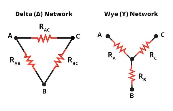
Wye-configured load banks are specialized testing devices that include a neutral connection, distinguishing them from the more common delta-configured load banks. This configuration allows for testing power sources under both balanced and unbalanced load conditions, offering enhanced flexibility to evaluate system performance across a variety of scenarios.
Key Features:
- Neutral Connection: The wye configuration includes a neutral point, enabling precise simulation of real-world electrical systems with neutral-dependent loads.
- Unbalanced Load Testing: Supports testing of power sources under uneven phase loading, critical for assessing system stability and performance in non-ideal conditions.
- Versatile Configuration: Can be adjusted to test single-phase or three-phase systems, accommodating a wide range of power source types and ratings.
Applications:
- Generator and UPS Testing: Evaluates the performance of generators and uninterruptible power supplies (UPS) under unbalanced loads, ensuring reliability in real-world applications where loads may not be evenly distributed.
- Data Center Commissioning: Simulates unbalanced load conditions to verify the stability of power distribution systems in data centers, where equipment may draw uneven power across phases.
- Industrial and Commercial Facilities: Tests power systems in environments with diverse loads, such as manufacturing plants or office buildings, to ensure robust operation under varying conditions.
- Compliance and Certification: Supports testing to meet standards that require evaluation of power systems under unbalanced load scenarios, ensuring regulatory compliance.
Considerations:
- System Compatibility: Ensure the power source and load bank are compatible with wye configuration, including proper neutral connection and phase ratings.
- Load Balancing Precision: Carefully configure the load bank to simulate specific unbalanced conditions, as incorrect settings may lead to inaccurate test results.
- Safety Protocols: Verify proper grounding and neutral connections to prevent electrical hazards during testing, especially in unbalanced load scenarios.
- Technical Expertise: Operating wye-configured load banks requires knowledge of electrical systems and load configurations to interpret results accurately.
Wye-configured load banks provide a powerful tool for testing power systems under realistic and challenging conditions, ensuring reliability and performance in diverse applications.
Lab Testing Load Banks
Lab testing load banks are high-precision testing instruments designed for controlled environments, featuring fine load-step increments and all three linear elements (resistive, inductive, and capacitive). These specialized load banks enable detailed simulation and evaluation of electrical performance, making them essential for research, development, and product design applications.
Key Features:
- High-Precision Load Resolution: Offers fine load-step adjustments for accurate control, allowing precise simulation of various electrical conditions.
- Comprehensive Load Elements: Integrates resistive, inductive, and capacitive components to replicate complex real-world load scenarios.
- Controlled Testing Environment: Optimized for laboratory settings, ensuring repeatable and reliable results under stable conditions.
- Customizable Configurations: Supports tailored setups to meet specific testing requirements, accommodating a wide range of power systems and devices.
Applications:
- Research and Development: Used to test and refine new power system designs, such as inverters, generators, or battery systems, under controlled load conditions.
- University and Academic Settings: Facilitates electrical engineering experiments and studies, enabling students and researchers to analyze system behavior and performance.
- Product Design and Validation: Supports the development and certification of electrical components, ensuring they meet performance and safety standards before market release.
- Prototype Testing: Evaluates the performance of prototypes under diverse load scenarios, identifying design flaws or inefficiencies early in the development process.
Considerations:
- Equipment Calibration: Regular calibration is essential to maintain the precision and accuracy of load-step increments and measurements.
- Test Environment Control: Ensure the lab maintains stable conditions (e.g., temperature, humidity) to avoid external influences on test results.
- Technical Expertise: Requires skilled operators with knowledge of electrical systems and load bank configurations to design and interpret complex tests.
- System Compatibility: Verify that the load bank’s capacity and load elements align with the specifications of the device or system under test.
Lab testing load banks are critical tools for advancing electrical engineering innovation, providing the precision and flexibility needed to develop and validate high-performance power systems in controlled research environments.
Microgrid Load Banks
Microgrid load banks are specialized testing tools designed to validate the performance and reliability of microgrids—localized power distribution systems that integrate renewable energy sources (e.g., solar, wind) and conventional generators. Microgrids provide resilient, flexible power solutions for facilities, communities, or remote sites, serving as primary or supplementary power sources. Rigorous load bank testing ensures proper commissioning, operation, and maintenance of these complex systems.
Key Features:
- AC and DC Configurations: Supports both AC and DC load testing to simulate diverse real-world conditions, accommodating the hybrid nature of microgrid power sources.
- High Versatility: Capable of testing multiple components, including engines, alternators, voltage regulators, and control systems, under varying load scenarios.
- Precise Load Simulation: Replicates dynamic load profiles to evaluate microgrid performance during startup, load changes, and steady-state operation.
- Scalable Design: Available in various capacities to match the scale and complexity of microgrid systems, from small community setups to large industrial networks.
Applications:
- Microgrid Commissioning: Verifies the performance of newly installed microgrids, ensuring all components operate cohesively under real-world conditions.
- Renewable Energy Integration: Tests the integration of solar, wind, or battery storage systems with conventional generators, confirming seamless power delivery and grid stability.
- Resilience Testing: Evaluates microgrid performance during grid outages or islanded operation, ensuring reliability for critical facilities like hospitals, data centers, or military bases.
- Maintenance and Optimization: Supports routine testing to identify performance issues, optimize control systems, and extend the lifespan of microgrid components.
Testing Capabilities:
- Engine Performance: Confirms the engine’s ability to deliver the required power output under varying loads.
- Voltage Regulator Response: Assesses the speed and accuracy of voltage regulation to maintain stable power delivery.
- Alternator Capability: Verifies the alternator’s ability to sustain consistent voltage and frequency across load conditions.
- Control System Reliability: Tests the microgrid’s control system for robust performance during load transitions and fault conditions.
Considerations:
- System Compatibility: Ensure the load bank’s AC/DC capabilities and capacity align with the microgrid’s power sources and load requirements.
- Dynamic Load Profiles: Configure the load bank to simulate realistic load patterns, including sudden changes, to accurately assess microgrid response.
- Environmental Factors: Account for site-specific conditions (e.g., temperature, altitude) that may affect microgrid performance during testing.
- Technical Expertise: Requires skilled operators to design and interpret tests, particularly for complex microgrids with multiple energy sources.
Microgrid load banks are essential for ensuring the reliability and efficiency of modern microgrid systems, supporting their growing adoption in sustainable and resilient power solutions.